+86 (0)574 62837603



Beyond semiconductor processing, FEP-encapsulated O-rings may be considered for selected chemical-processing, laboratory, pharmaceutical, food-processing and specialty-fluid applications. Their FEP outer sheath can provide a chemically resistant contact surface, while the elastomer core contributes to the seal structure and compression behavior. However, suitability depends on the actual fluid, temperature, pressure, sealing motion, core material and any applicable compliance requirements. An industry label alone is not enough to establish suitability.
Semiconductor processing is the best-documented starting point — global semiconductor manufacturing equipment sales were 113billionin2024,forecasttoreach113 billion in 2024, forecast to reach 113billionin2024,forecasttoreach139 billion in 2026 (SEMI Year-End Total Semiconductor Equipment Forecast). This article does not repeat that story; it looks at the equipment and fluids outside the fab where the same inert contact surface is worth evaluating — and where it needs to be verified before it is recommended.
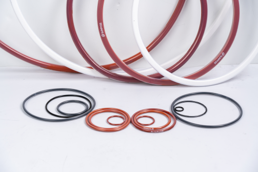
An FEP-encapsulated O-ring is a two-part structure: a chemically inert fluoropolymer sheath around an elastomer core. Each part does a different job, and both must be evaluated.
The FEP sheath provides the contact surface that meets the fluid. It is rated "excellent" for chemical and solvent resistance per ASTM D543 (Teflon™ Product Selection Guide).
The elastomer core provides the elasticity that pushes the seal against its mating surface, so it sets most of the compression and recovery behaviour. The elasticity comes from the core; the chemical resistance comes from the seamless FEP encapsulation (FEP/PFA encapsulated O-ring construction reference).
Encapsulated O-rings are designed mainly for static sealing; the FEP jacket is not built to flex repeatedly under dynamic pressure cycling (O-Ring Supply Co., FEP encapsulated O-rings).
FEP appears in published tables with several different numbers, and this is the most common source of confusion. The figure below separates three data types, which should never be used interchangeably.
|
Data type |
Correct use |
|
FEP raw-material melting point |
Describes a thermal property of the material — not a use temperature |
|
FEP material continuous-use reference value |
A material reference only; must carry its source and applicable conditions |
|
Specific FEP-encapsulated O-ring working temperature range |
The basis for product selection; must be supported by that product's technical documents |
For reference, FEP melts near 260 °C (500 °F) and is commonly listed with a material continuous-use reference around 204 °C (400 °F) — a property of the material, not a rating for any product (Fluorotherm material comparison; Teflon™ Product Selection Guide).
The whole seal, not the sheath, sets the usable range. Composite ranges quoted elsewhere for encapsulated O-rings (commonly written as about −60 °C to 260 °C) belong to the suppliers and structures that published them, with the sheath setting the upper limit and the core the lower. The range that matters for a purchase is the one printed on the specific product's datasheet, and it is covered in the selection section below.
Do not assume: a temperature range published by another supplier applies to a SUNPASS product. Quote a working range only for the specific product and core material, against that product's own documentation.
Figure: a real cross-section photograph, labelling the FEP sheath and the actual core material. SUNPASS's standard FEP O-ring uses a silicone (VMQ) core, so label it VMQ and label FKM/Viton separately where that core is used — do not describe all FEP-encapsulated O-rings as sharing one core material.
The table gives the application landscape; the sections below expand the priority directions and answer three questions for each: what limits a standard elastomer there, what an FEP-encapsulated structure could offer, and what makes it unsuitable or needs verification.
|
Industry |
Equipment / fluid to evaluate |
Main selection concerns |
|
Chemical processing |
Transfer pumps, valves, metering systems, static connections |
Fluid compatibility, core material, temperature and pressure |
|
Laboratory and analytical equipment |
Analytical-instrument fluid paths, reagent delivery connections |
Reagent compatibility, dimensional accuracy, contamination control |
|
Pharmaceutical and bioprocess |
Selected process fluids and auxiliary systems |
Product documentation, hygienic design, cleaning requirements |
|
Food and beverage |
Fluid-handling equipment confirmed as suitable |
Food-contact requirements, cleaning conditions, compliance documents |
|
Paint, coating and specialty fluids |
Coating metering and specialty-fluid dispensing equipment |
Solvent compatibility, pressure and temperature |
These are application areas to evaluate, not a guarantee of suitability for every system or a claim of existing SUNPASS customer installations.
Equipment / fluid scenario: chemical transfer pumps, diaphragm and metering pump heads, valves, and the static joints and flange connections around them — the positions where the fluid is still concentrated and the seal is not continuously moving.
What limits a standard elastomer: many process media cause ordinary elastomers to swell, harden or otherwise change performance, and these pump- and valve-body seal positions are often among the first to fail.
What FEP encapsulation may offer: the fluid meets an inert FEP contact surface instead of the core, so an elastomer that would otherwise be unsuitable can be protected behind the sheath. This is the trade-off encapsulated seals exist to solve: a standard elastomer lacks the chemical resistance, while a solid PTFE part lacks the elasticity needed for reliable long-term fluid sealing (SUNPASS FEP Encapsulated Seal).
When it is not suitable / must verify: the sheath only protects where it is intact and where the seal stays static. A diaphragm or metering-pump head that flexes the seal is a different duty from a fixed flange joint, and a structure designed mainly for static sealing should not be assumed suitable for repeated flexing. Confirm medium and concentration, core material, temperature, pressure, and whether the position is static or dynamic; if core compatibility, sheath integrity or the equipment conditions cannot be confirmed, do not recommend on the FEP name alone.
Equipment / fluid scenario: reagent delivery lines, valve and connector positions, and fluid-path components in analytical instruments and general laboratory fluid handling.
What limits a standard elastomer: reagents can attack common seal materials, and contamination control makes any swelling, leaching or particle shedding unacceptable — even a trace of extracted material can distort an analysis.
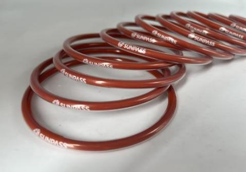
What FEP encapsulation may offer: for certain reagents and tight dimensional requirements, an inert contact surface with controlled dimensions can be evaluated. SUNPASS OEM data list an FEP-coated O-ring diameter range of about 1.5–30 mm, which suits instrument-scale fluid paths (SUNPASS OEM service).
When it is not suitable / must verify: reagent composition or dimensional requirements that are unclear should not be fixed to a material and size directly. Confirm the reagent list, the required inner diameter and cross-section, the cleaning or sterilisation step, and any documentation the instrument manufacturer requires.
Equipment / fluid scenario: specific process-fluid systems and some metering and valve equipment that must meet defined cleaning and hygiene requirements.
What limits a standard elastomer: sealing materials must not introduce contamination and must survive cleaning or sterilisation.
What FEP encapsulation may offer: when the structure and documents of a specific product match the equipment requirements, suitability can be evaluated.
When it is not suitable / must verify: treat compliance as a verification condition, not a default. Confirm the actual regulatory requirements, the product documents and the cleaning or sterilisation conditions; without the corresponding documents, do not claim compliance with FDA, USP Class VI or other specific requirements
Equipment / fluid scenario: fluid metering, valves and fluid-handling systems confirmed for the specific duty
What limits a standard elastomer: food-contact compliance, cleaning compatibility and operating stability.
What FEP encapsulation may offer: for seals that already meet the relevant product requirements, an encapsulated structure can be evaluated.
When it is not suitable / must verify: chemical resistance is not the same as food grade. 21 CFR 177.1550 permits PTFE and FEP perfluorocarbon resins as food-contact articles at the material level (eCFR 21 CFR 177.1550) — a material permission, not a finished-product certification — so keep food-contact compliance as a document to obtain, not a default.
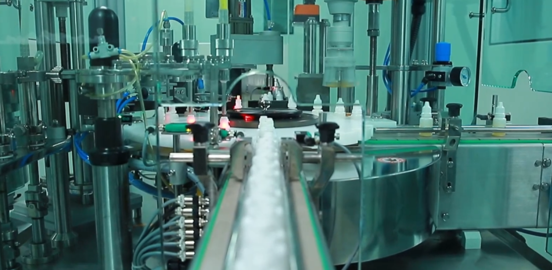
Equipment / fluid scenario: coating metering equipment and specialty-fluid dispensing systems handling solvents, additives and cleaning media.
What limits a standard elastomer: certain solvents, additives and cleaning media may be incompatible with ordinary seal materials.
What FEP encapsulation may offer: an FEP-encapsulated O-ring can be evaluated as a candidate structure.
When it is not suitable / must verify: confirm the actual fluid list, concentration, operating temperature, pressure and core material. Where application evidence is lacking, describe the direction as potential only — not as an existing SUNPASS customer case.
Chemical resistance alone does not guarantee sealing performance. For hazardous or highly permeable media, confirm the suitability of the complete seal structure under the actual operating conditions.
Space-allocation rule: chemical and laboratory applications can be expanded as the priority directions; the length given to the other industries should follow keyword data, real product documents and citable industry sources rather than being spread evenly.
Keep two questions apart: which material suits a duty, and which complete seal structure suits an item of equipment. Comparing "FEP vs PFA vs solid PTFE" as materials answers only the first. A solid PTFE part and an FEP-encapsulated elastomer O-ring differ in structure, elasticity, contact method and installation, so they cannot be ranked by melting point or continuous-use temperature. Compare only the dimensions that change the buying decision:
|
Comparison dimension |
Question to confirm when selecting |
|
Chemical compatibility |
Is it suitable for the actual medium, concentration and temperature? |
|
Temperature and pressure range |
What are the permitted ranges of the sheath and the core separately, and at what pressure? |
|
Static or dynamic use |
Must the seal withstand motion, friction or repeated cycling? |
|
Recovery and compression behaviour |
Can the structure meet the actual compression and sealing requirement? |
|
Dimensions and installation |
Do the size, cross-section and installation method fit the equipment? |
|
Compliance documents |
Is there product-level documentation and test data for the target industry? |
PFA's advantage over FEP is a higher temperature ceiling — about 260 °C versus FEP's 204 °C material reference (Fluorotherm material comparison). Mention it briefly where hot service is the constraint; if FEP vs PFA carries independent search demand, treat it as a separate in-depth comparison article.
This is the information list a buyer can send directly for a quotation or a technical discussion:
Fluid or chemical name and concentration
Normal and peak operating temperature
Working pressure and pressure fluctuations
Static or dynamic sealing conditions
Required inner diameter and cross-section
Core material requirements
Cleaning and sterilisation conditions, if applicable
Applicable compliance documents and traceability requirements
Working temperature is a product figure, not a sheath figure. SUNPASS publishes a value on each product page rather than one range for "FEP O-rings": the FEP O-ring page quotes −60 °C to +150 °C, the FEP Encapsulated Seal (manlid) page quotes −60 °C to +200 °C continuous, and the OEM reference table lists −60 °C to +200 °C for an FEP sheath over a silicone core and −60 °C to +260 °C for a PFA sheath over a silicone core. Quote only the figure on the datasheet of the part being bought (SUNPASS FEP O RING; SUNPASS OEM service).
Need help selecting an FEP-encapsulated O-ring? Send us the fluid name and concentration, operating temperature, pressure, required dimensions and sealing conditions, and SUNPASS can evaluate the available structure against your application requirements. Send a selection request.
SUNPASS states suitability only against the corresponding product's real documents. The values below are taken from SUNPASS product pages; each figure belongs to a named product and core material and is not transferable to another.
Sheath and core structure: a seamless FEP encapsulation over a silicone (VMQ) elastomer core is standard for the FEP O-ring; an FKM/Viton core and a PFA sheath are available options. The SUNPASS FEP Encapsulated Seal for manlids uses the same seamless FEP-over-silicone-or-Viton construction (SUNPASS FEP O RING).
Verified dimensions and tolerances: listed stock items FO00003 (3″ footvalve O-ring) and FO00004 (2.5″ PRV/safety-relief valve); the FEP O-ring page quotes a wire-diameter tolerance of ±0.1 mm and an inner-diameter tolerance of +0/−0.2 mm. OEM data list an FEP-coated O-ring diameter range of about 1.5–30 mm, with PFA around 2.4–30 mm (SUNPASS OEM service).
Verified working temperature per product: the range is product-specific and core-dependent — −60 °C to +150 °C on the FEP O-ring page, −60 °C to +200 °C continuous on the FEP Encapsulated Seal (manlid) page, and, in the OEM reference table, −60 °C to +200 °C for an FEP sheath over a silicone core and −60 °C to +260 °C for a PFA sheath over a silicone core. Quote only the figure on the datasheet for the part being bought.
Customisation on offer: circular and square cross-sections, non-standard sizes, FEP/PFA/silicone/fluorine coating, and logo or part-number printing (SUNPASS OEM service).
Documents and images: ISO 9001:2015, SGS and TUV certification, a REACH statement, an FDA test report and a USP Class VI declaration letter for FEP/PFA-over-silicone parts, and a per-batch QC report giving dimensions, hardness and a traceability code.
A continuous-use ceiling must not be quoted as a single figure for "FEP O-rings"; it belongs to a named product and a named core material. Confirm each figure against the current datasheet, and add a real cross-section photo labelling the sheath and the core material.
Sunpass Sealing Technology (Zhejiang) Co. LTD
• Zhejiang Top Sealing and Insulation Co.,Ltd.
• Echo Industry Limited
• Tenglong Sealing and Thermal Insulation Manufactory
 English
 русский
 Español
 Add: No. 78 West Road Zhenxing, Lianghui Industry Zone, Yuyao, Zhejiang, China
 Tel: +86 574 62837603
 E-mail: